![]() Ok, so I was trapped in quarantine, and thought I’d build a controller for a random person. The request was simple- 4 switches sending CC commands.
Ok, so I was trapped in quarantine, and thought I’d build a controller for a random person. The request was simple- 4 switches sending CC commands.
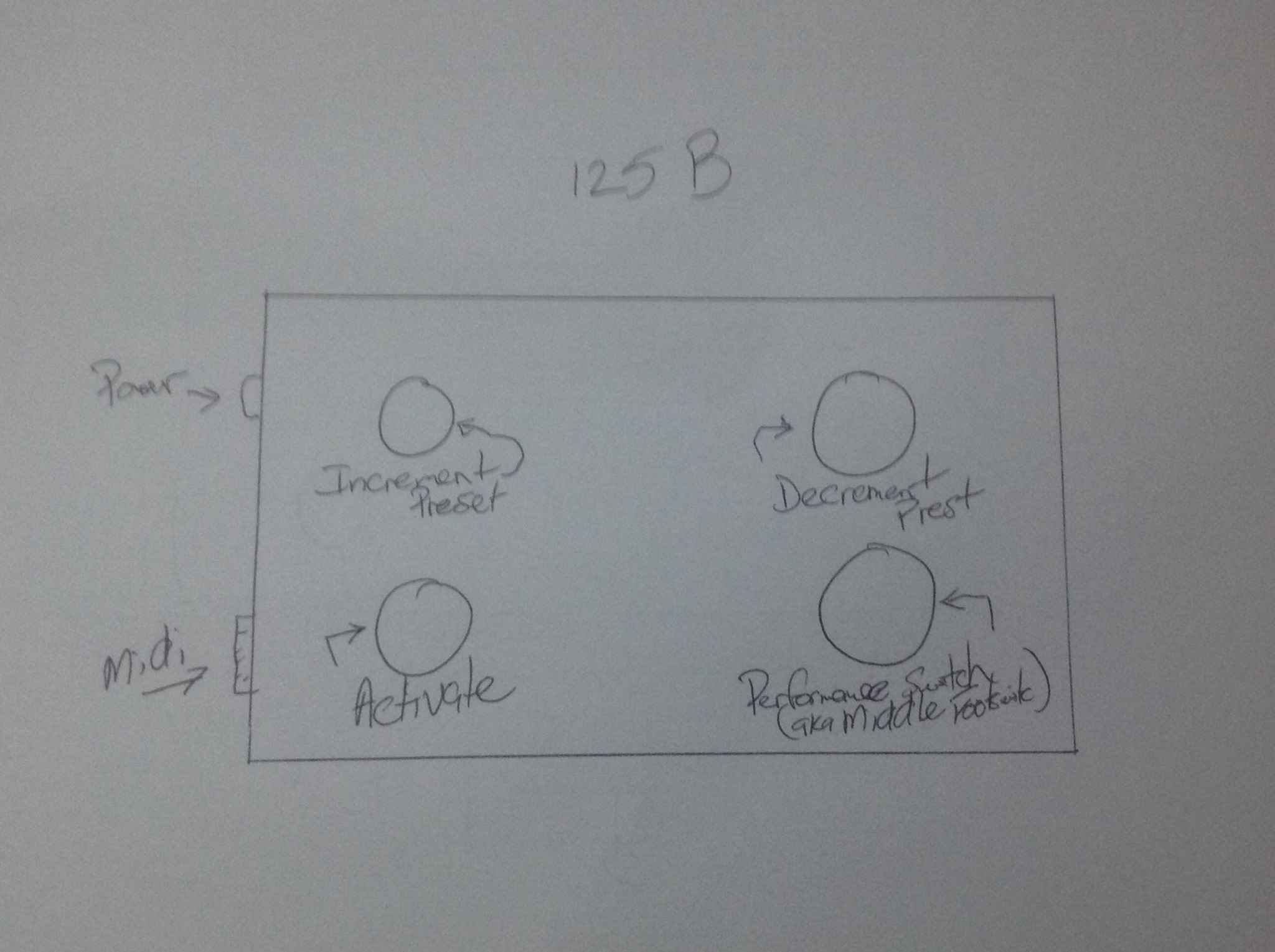
Here is the plan:
So, this is easy. Partslist here- total is about $40 with shipping:
Main Board- Ardruino NANO EVERY $11.00 –I burnt out a couple of the $5 knock-offs I was using, so I switched to the name-brand board for a bit. I think the knock-offs would be fine, though.. so a NANO clone would work here. It is probably overkill, but meh.
Enclosure $7.90
Switches 4x$2.09 $8.36
LED $1.15
power jack $0.75 (note- I dont love this jack. )
fancy nuts 4x$0.82 $3.28 (cheap bling)
Midi Jack $1.50
–you also need a 220 OHM resistor, which costs $0.06, but you have to buy 100 🙂
So- the enclosure is a little tight for 4 switches, so I went with an offset Layout;
Drilling was easy. I am please with these step bits.:
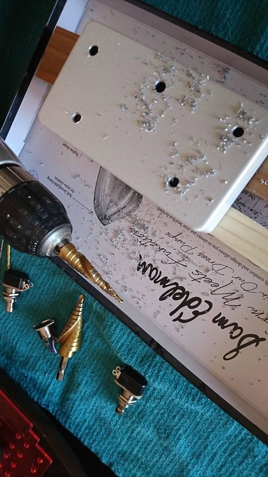
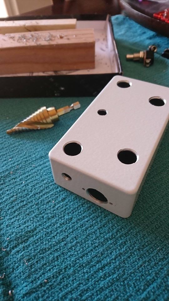
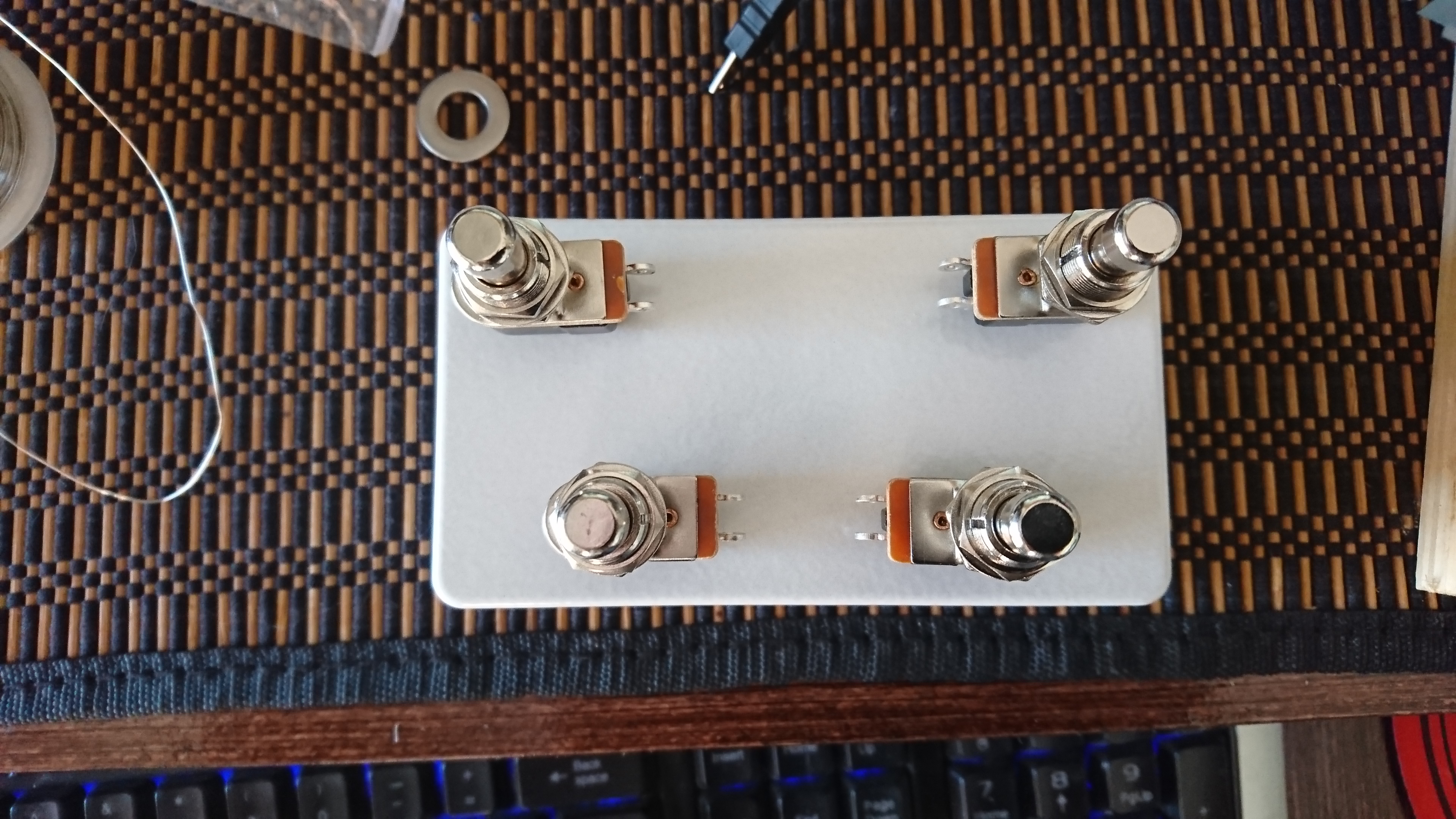
Comes out nice and clean. Test fit everything and its good. The power jack and the switch were ~almost~ too close. I got lucky.
So then it’s just soldering it up:
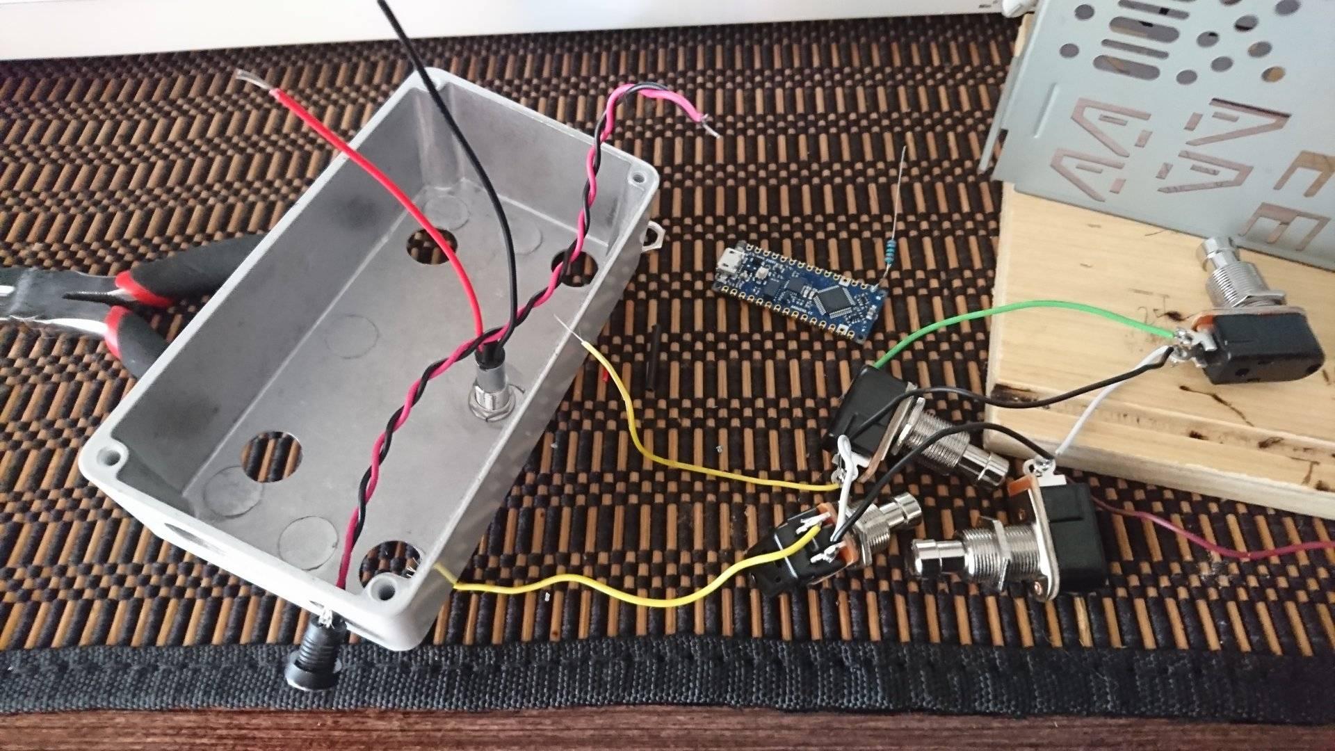
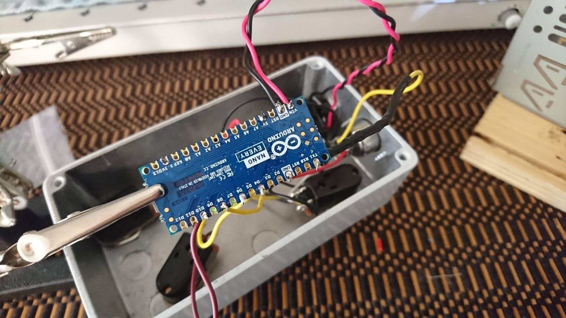
How did I wire it? I used a common ground all around the switches, and ran ONE groundwire from a switch to the board
POWER JACK:
Negative tip to go with BOSS wiring. Positive to VIN, negative to Ground on board
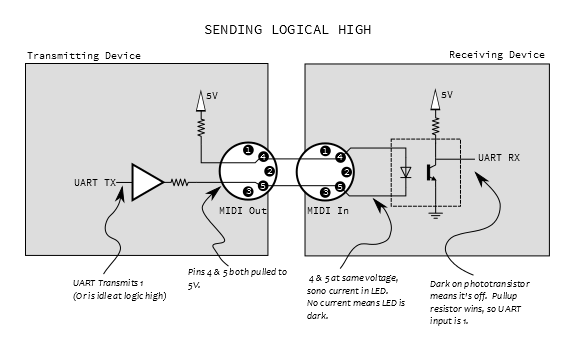
Typical MIDI wiring:
TX–>220 Ohm Resistor –> PIN 5
5v from NANO board–> PIN 4
Ground to PIN 2
This image is helpful, though it doesn’t have the ground:
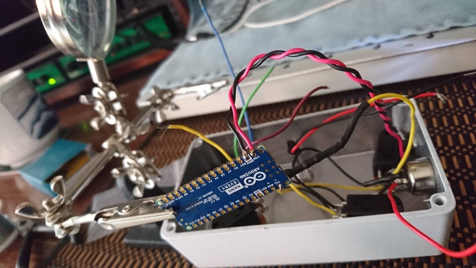
The LED is pre-resistored, so I just ran red to the 3.3V output. I think LED’s are too bright generally, but 5V would work too. Ground to Ground.
And the switches I wired to pins 4, 6, 8, and 10. This board can support 12 switches on the digital pins alone, so it is a good board for these projects. It also has a flat backside, so once it was wired and tested, I stuck it to the case with double-sided tape.
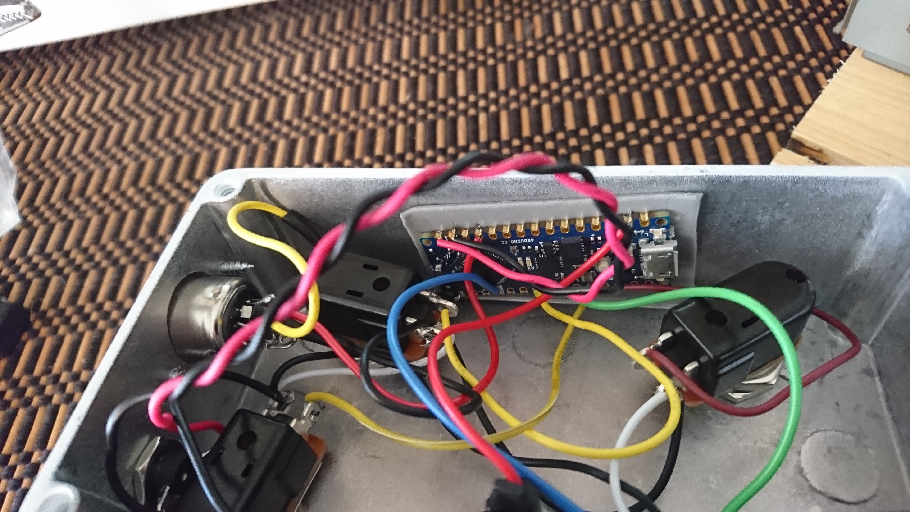
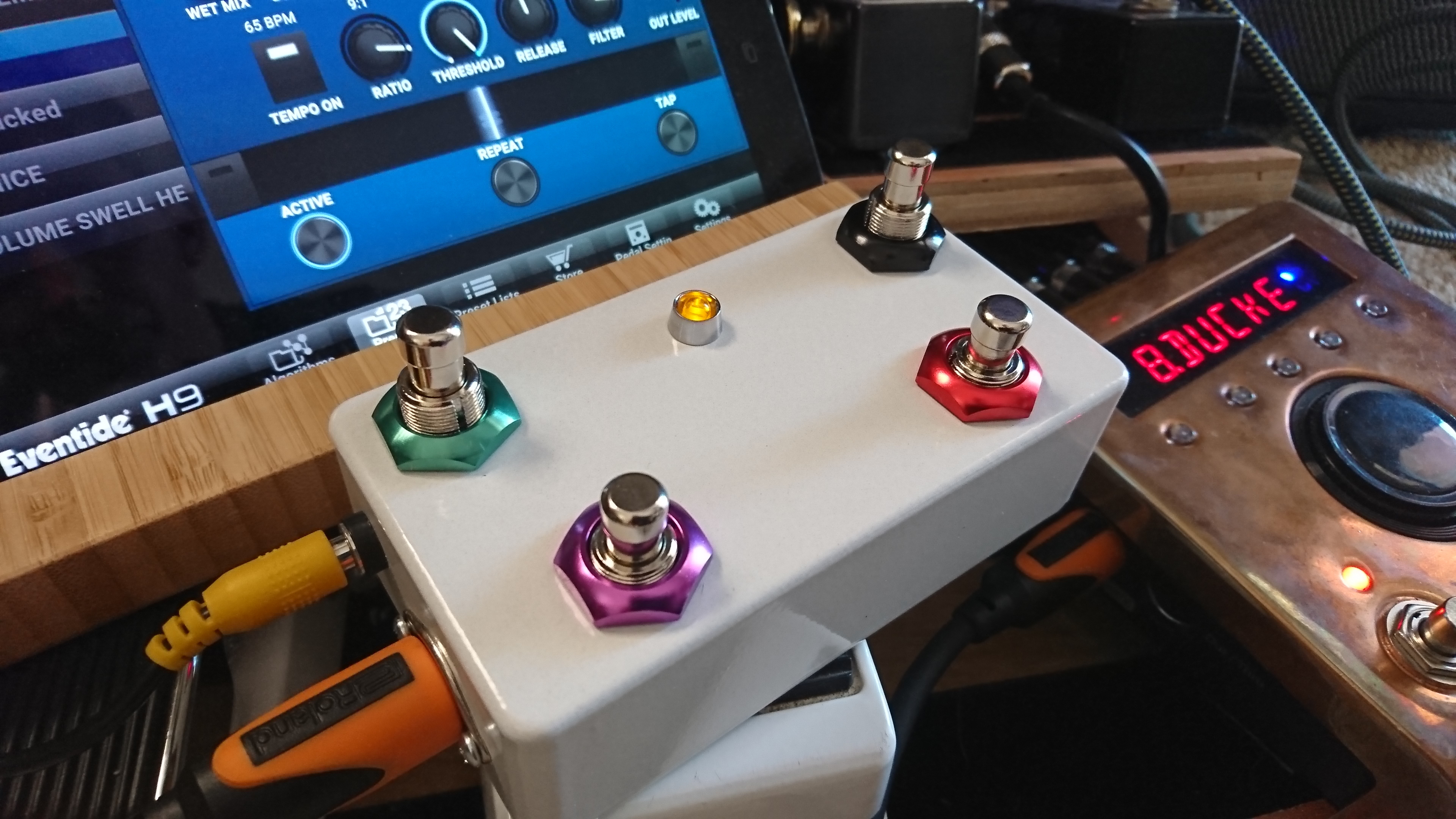
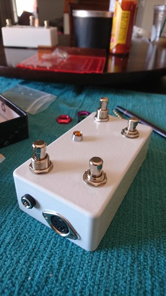
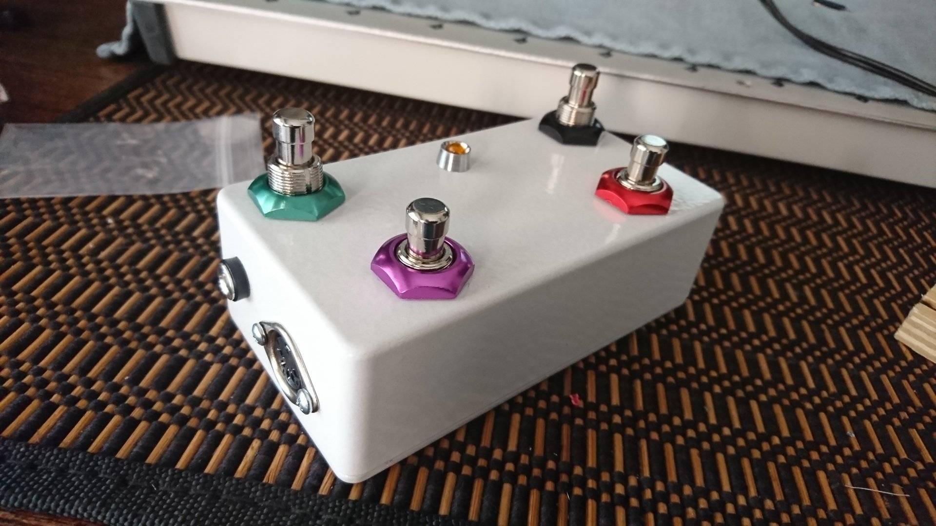
Final look? Looks great. The fancy nuts give it some bling.
The code is below. I used the Arduino IDE for this, with Peiter P’s great library:
https://github.com/tttapa/Control-Surface
and a dependency library:
https://github.com/PaulStoffregen/Encoder
Notably, the encoder library failed if I used the IDE repository version- I needed to manually install the latest from github.
Finally, here is the code.
I used my previously documented code for this.. stripped down for these 4 switches only. All MIDI CC on Channel 1
//midi.controller for eventide H9
 //by Cameron Newell @the.nw.enterprise, https://thenorthwestenterprise.com/
 //Library Source https://github.com/tttapa/Control-Surface
 //Built for Ardruino NANO EVERY

#include <Control_Surface.h> // Include the library

// Instantiate a MIDI interface
 USBDebugMIDI_Interface usbmidi(115200); // for serial monitor in ide
 //HardwareSerialMIDI_Interface serialmidi = {Serial1, MIDI_BAUD}; //for normal operation

/*Hotswitch or other cc function
 Will fire 127 on press and 0 on release. Use a momentary switch, like the others.
 Assign CC number from here:
 https://tttapa.github.io/Control-Surface-doc/Doxygen/d4/dbe/namespaceMIDI__CC.html
 https://www.midi.org/specifications-old/item/table-3-control-change-messages-data-bytes-2
 For reference {PHYSICALPIN, {MIDI_CC::NAMEOFCC#, CHANNEL_1},{ VALUEWHNPUSHED, VALUEWHENRELEASED }};
 */

 CCButton button10 = {10, {MIDI_CC::General_Purpose_Controller_1, CHANNEL_1},}; //Hotswitch RIGHT front CC#16
 CCButton button08 = {8, {MIDI_CC::General_Purpose_Controller_2, CHANNEL_1},}; //Decrement Left Rear CC#17
 CCButton button06 = {6, {MIDI_CC::General_Purpose_Controller_3, CHANNEL_1},}; //Increment Right Rear CC#18
 CCButton button04 = {4, {MIDI_CC::General_Purpose_Controller_4, CHANNEL_1},}; //Toggle Bypass LEFT Front CC#19

void setup() {
 Control_Surface.begin(); // Initialize Control Surface
 }

void loop() {
 Control_Surface.loop(); // Update the Control Surface
 }
One Last Glam Shot