![]() OK, I have published a couple of these..but I thought I would do a proper writeup again, since I have learned a lot a streamlined my methods.
OK, I have published a couple of these..but I thought I would do a proper writeup again, since I have learned a lot a streamlined my methods.
This is a how-to on a MIDI foot controller. It is specifically for the Eventide H9, but it can send any PC of CC messages you want, so you could build one for anything. The costs are reasonable, it takes a couple hours, and the code is easy.
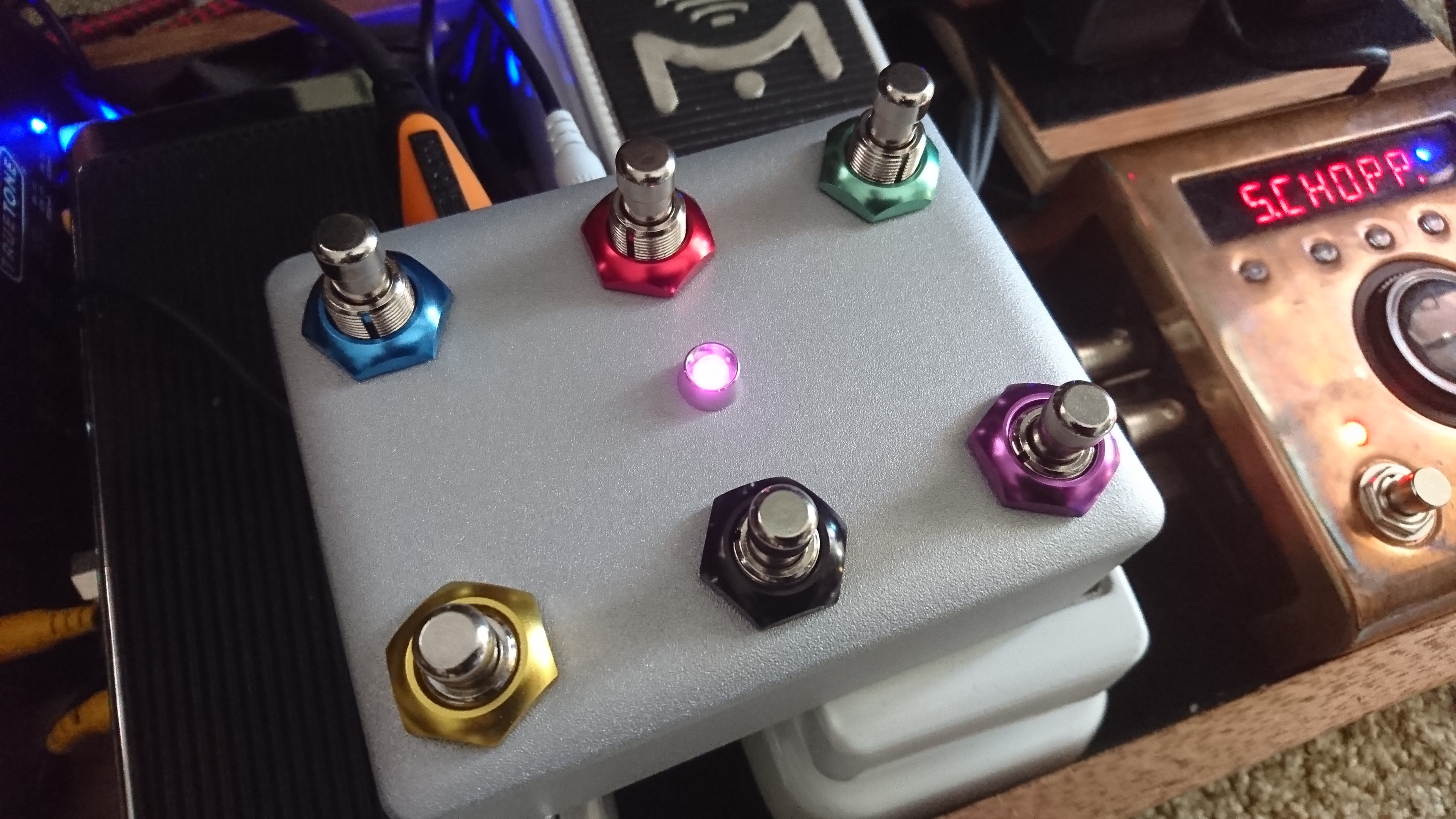
Here’s the latest:
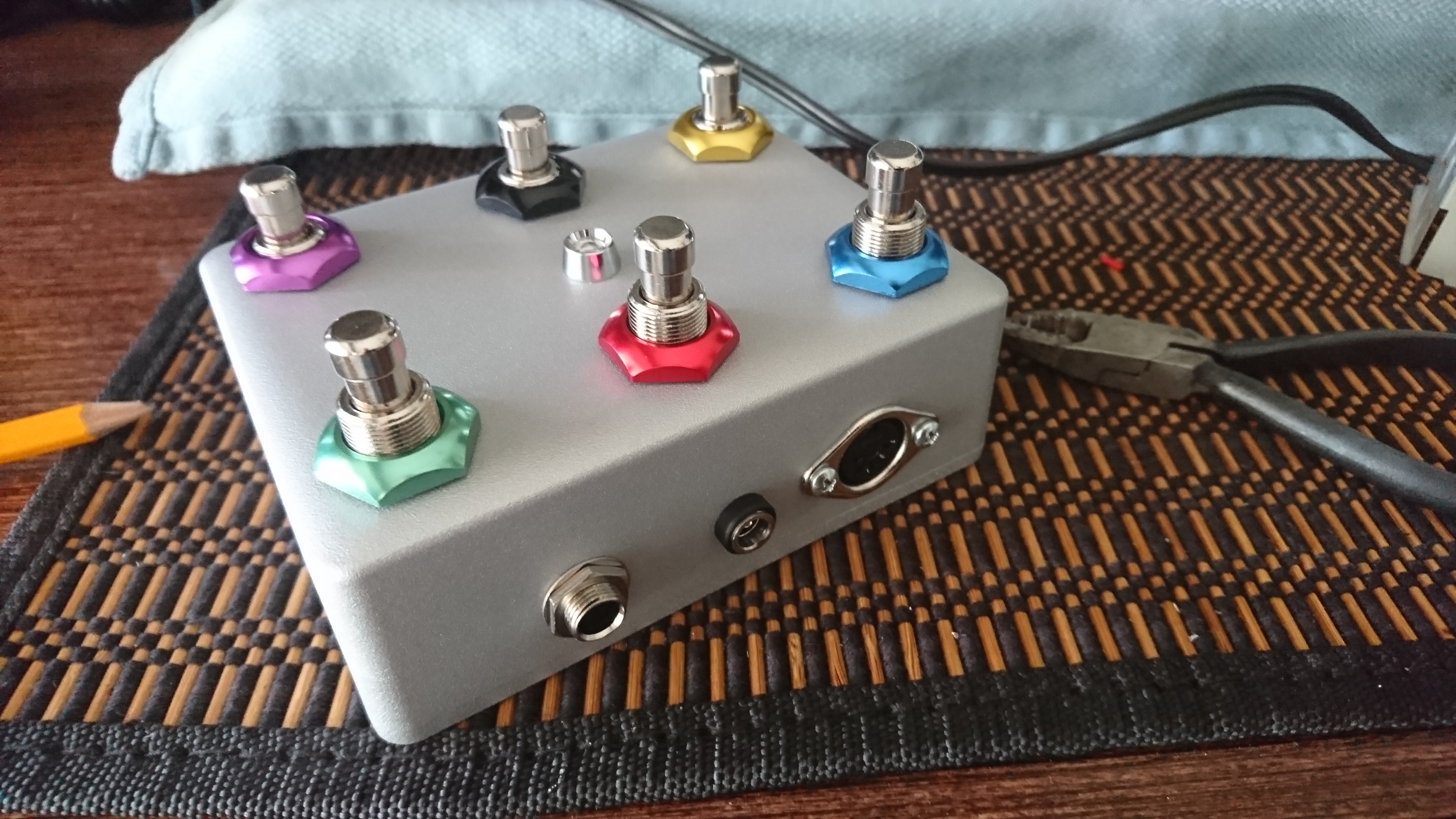
This is a six button control, all PC messages on the back line, CC messages on the front line that fire 127 when pressed, and 0 when released. It also has a jack for an Expression pedal on the back. It outputs standard 5-PIN MIDI, and requires some nominal voltage.
TOOLS NEEDED:
A drill
a soldering iron
some wire snips and stuff.
PARTS LIST:
TOTAL ~$50. Notably, this was a pretty fancy enclosure, you can get them cheaper, or cannibalize whatever you have.
| Nano EVERY Board | $11.00 | ||||
| Enclosure | $14.95 | ||||
| Switches | 6 | x | $2.09 | is | $12.54 |
| fancy nuts | 6 | x | $0.85 | is | $5.10 |
| LED | $1.80 | ||||
| power jack | $1.25 | ||||
| Midi Jack | $1.50 | ||||
| 1/4″ Jack | $1.59 |
Additionally, you need some random stuff.
–Wire. Whatever you have around. 22g Stranded is best.
–a capacitor for the EXP pedal (0.1uF)
–a couple screws #4, 3/8″ pan head
I am using the Arduino NANO EVERY board for these right now. Why this?
a) it has a wide input voltage range. I was using some off-brand nano clones, but I fried a couple. This takes up to 21V no problem.. and as the H9 has a 12V adapter, I appreciate it. That said, ANY board would work for this. The NANO EVERY is overkill.
b) it is cheap and good.
c) it has a flat backside, so I can just doublestick tape the board to the case for mounting simplicity.
The BUILD:
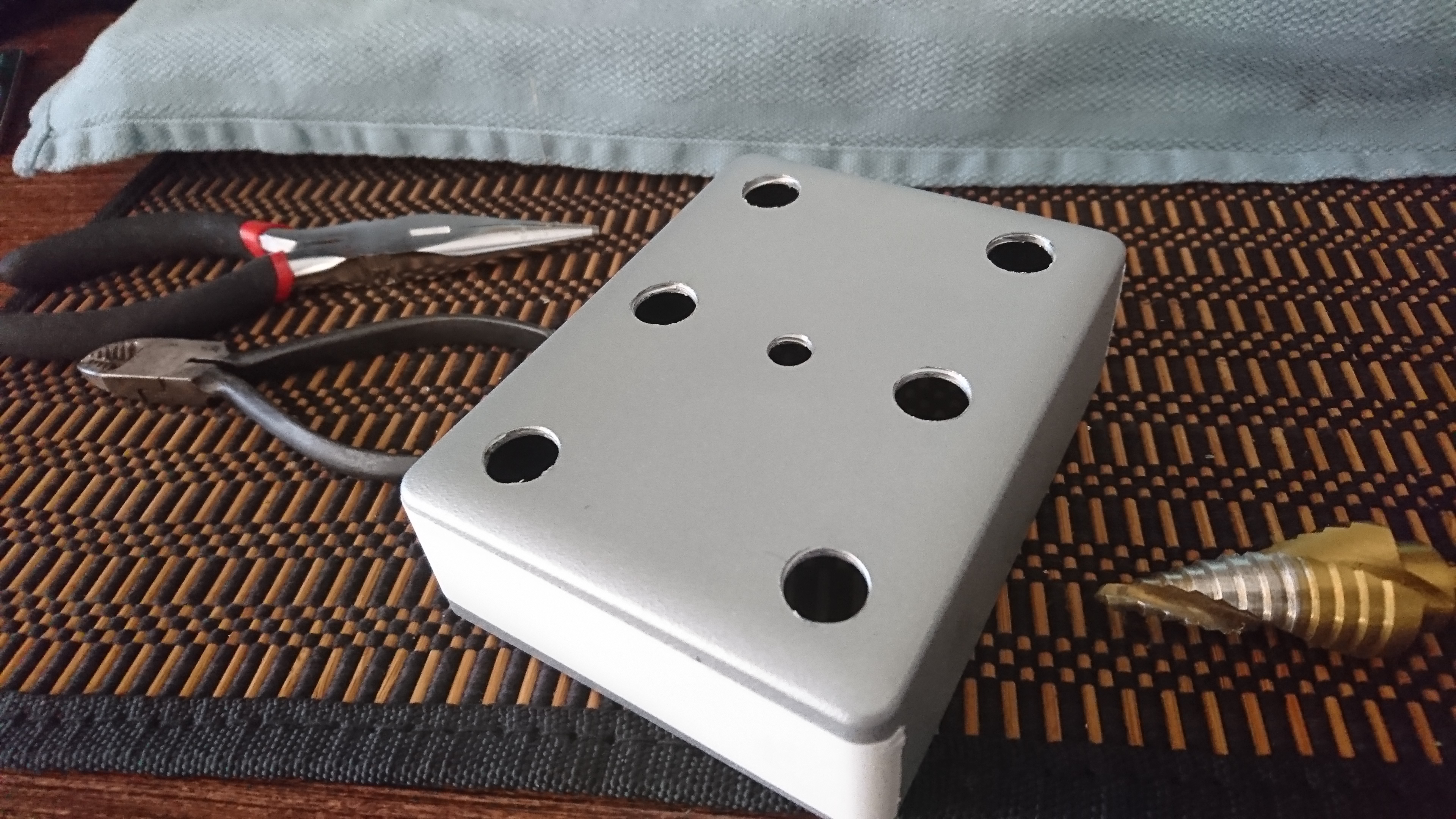
As I have written before, drilling aluminum is not hard, I use a regular cordless drill. I do advise using STEP BITS, however.. they make it a lot easier.
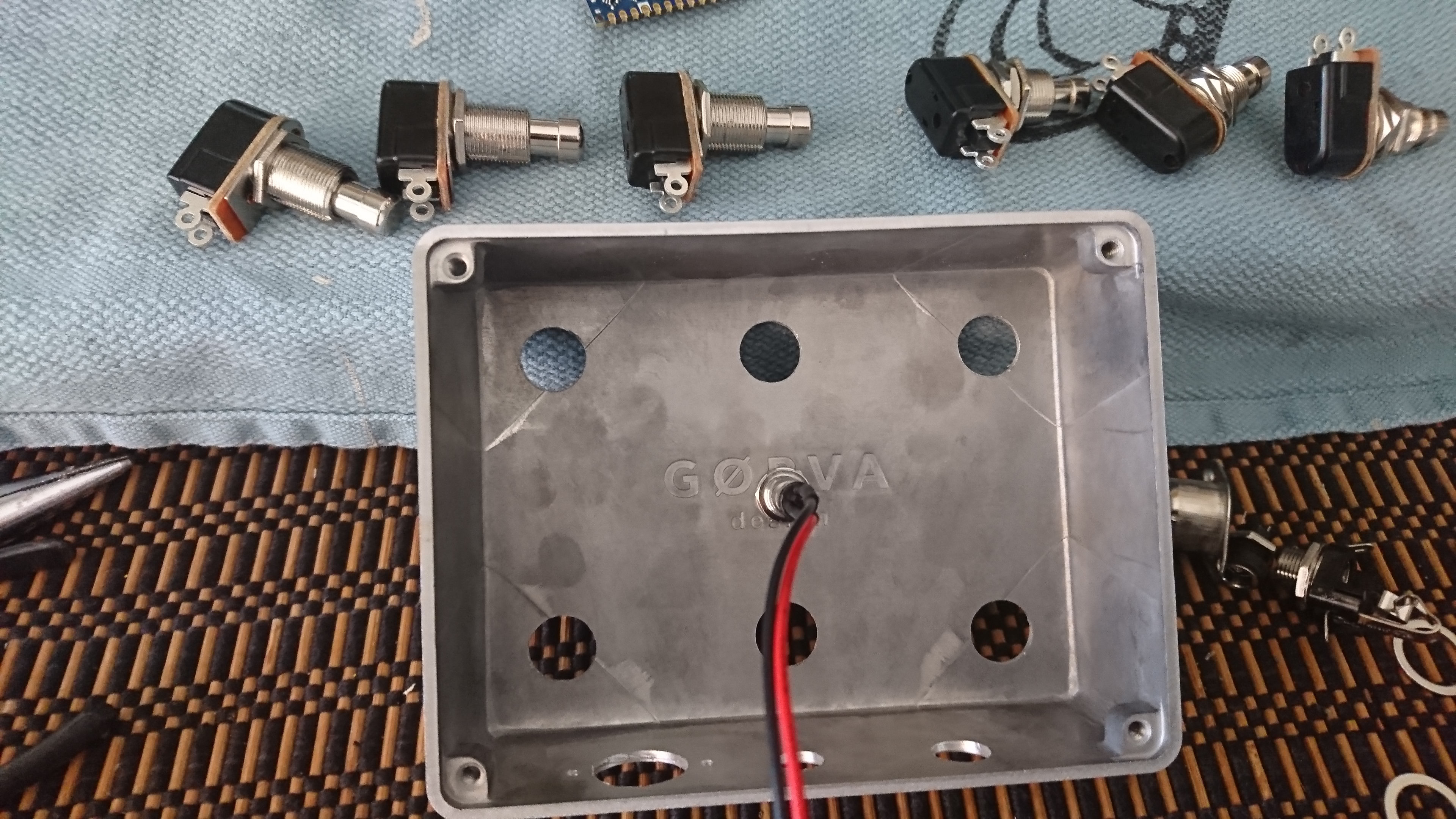
Drilling is straightforward. Do the top first:
Then make sure you have room for the backside clearance
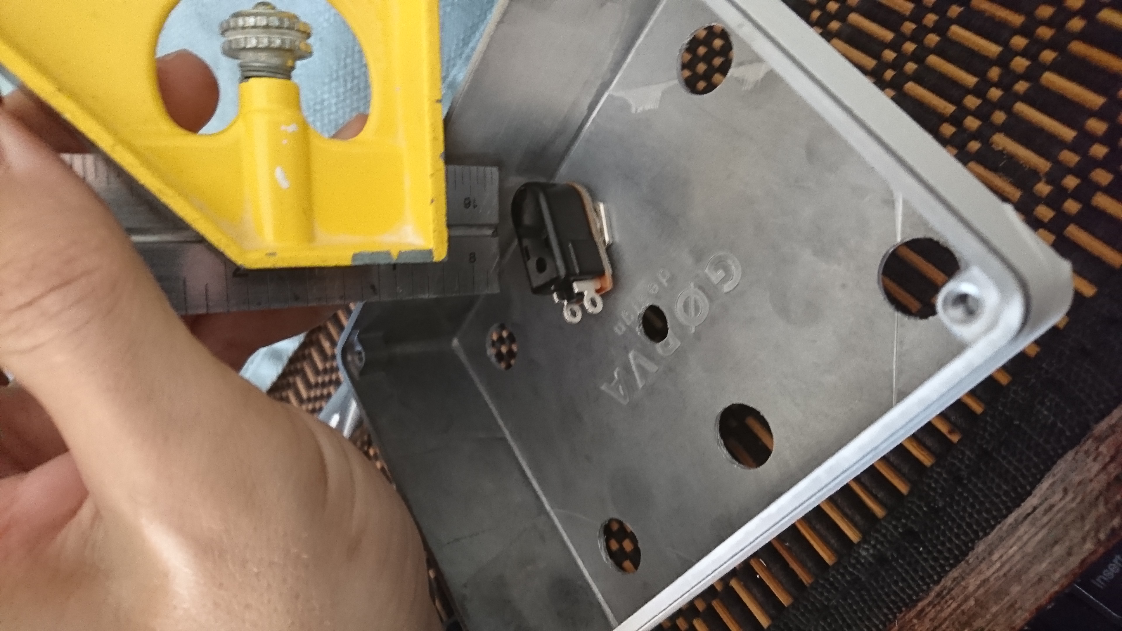
Then drill the back. I had to go low to get everything in, this was a tight case:
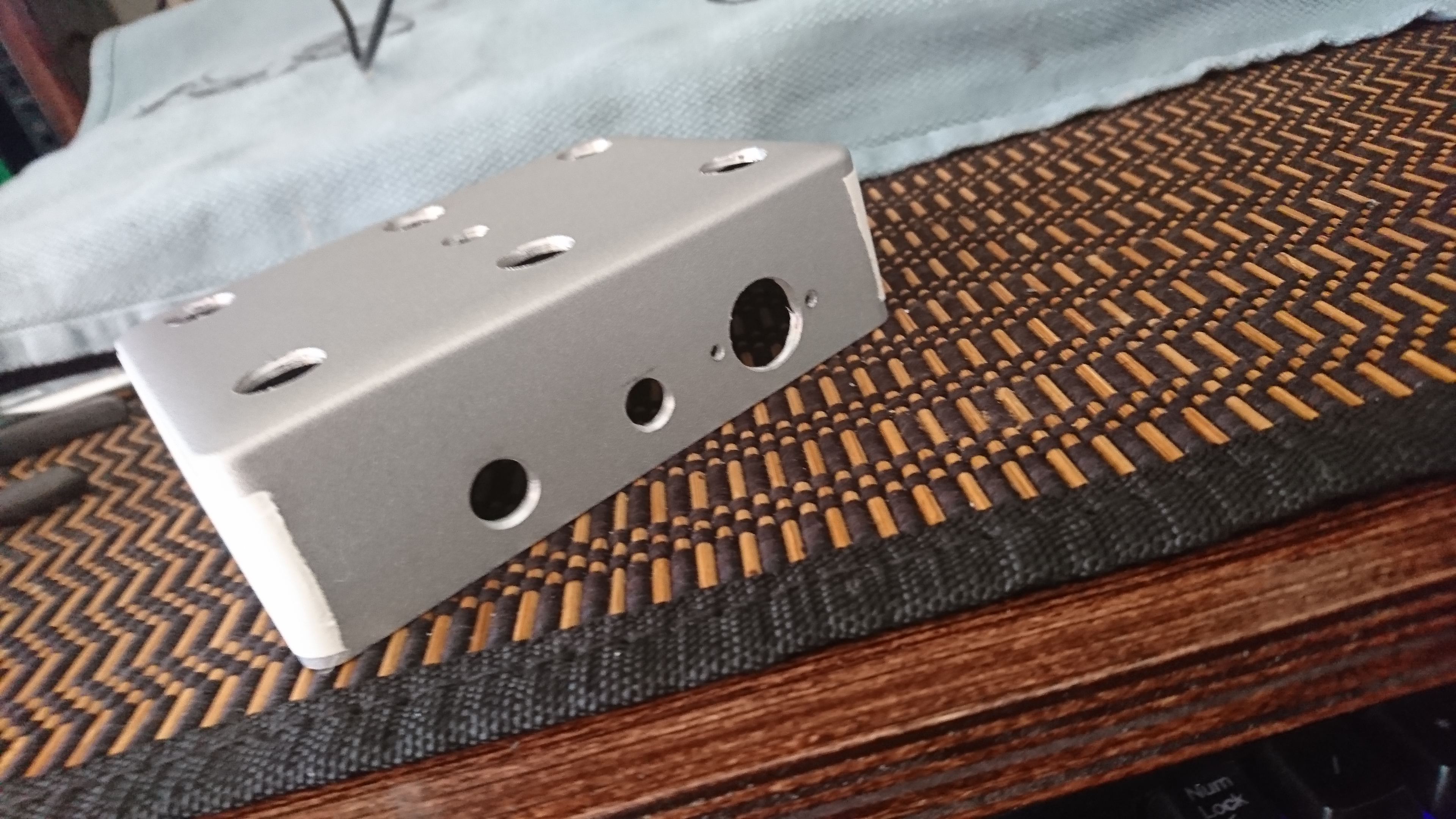
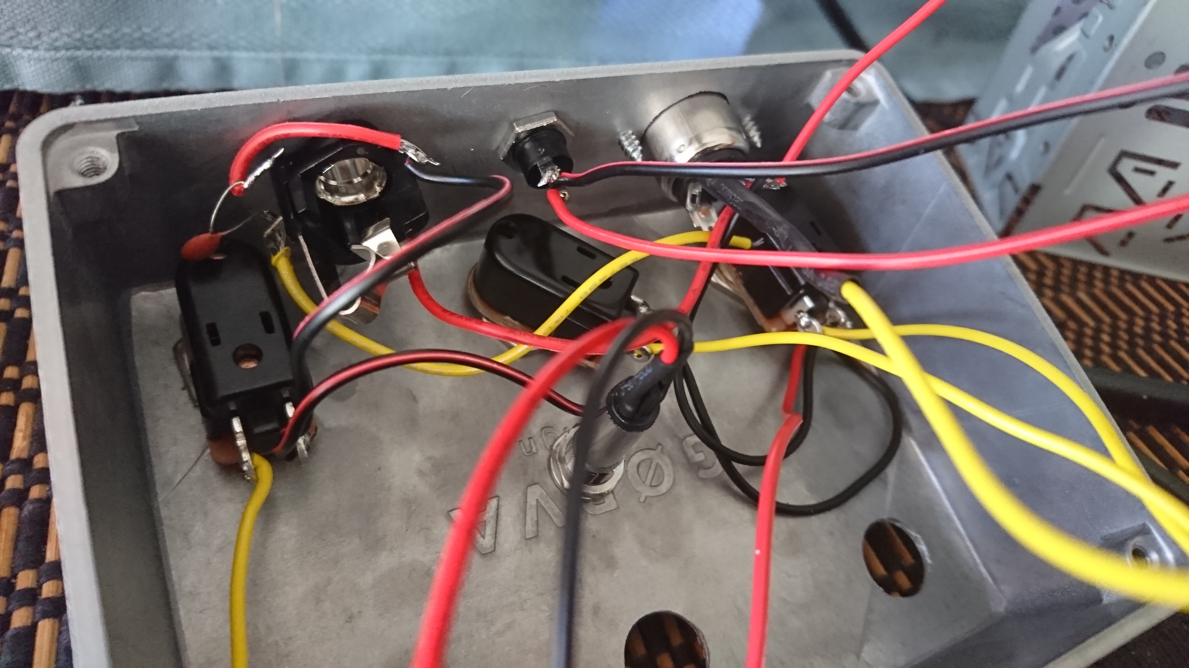
But a NICE case. Here are some shots of how I stagger the switches: all the nuts on the front row.
A good look on the resistor on the MIDI connector
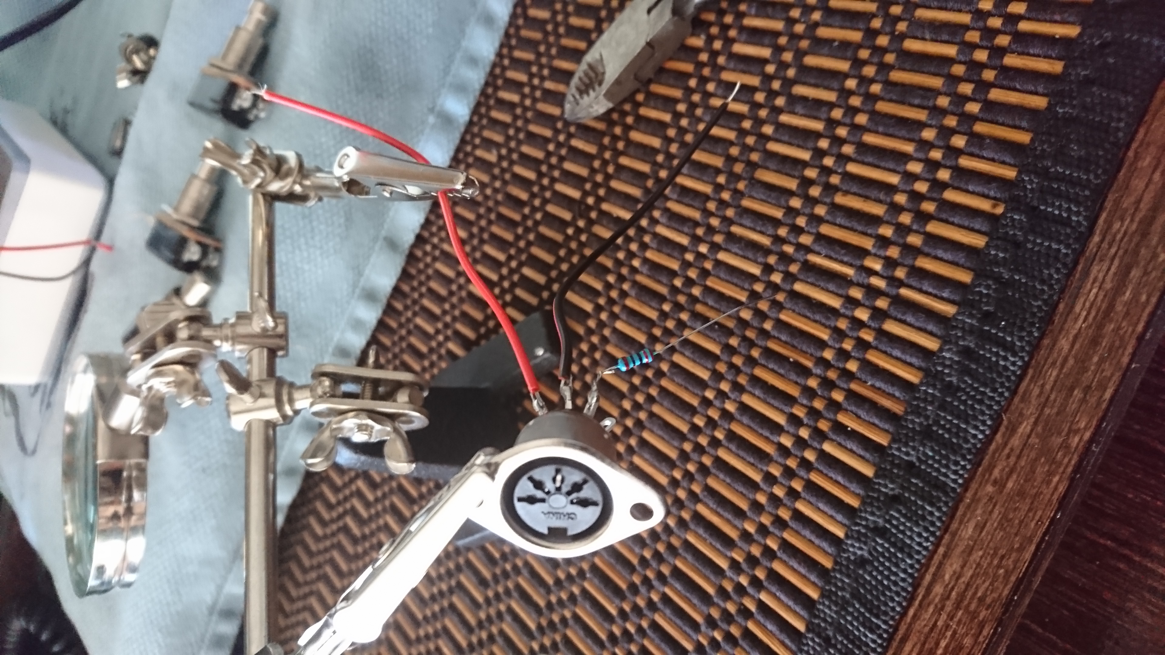
This is useful every time. The ground is on 2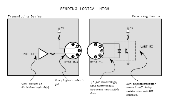
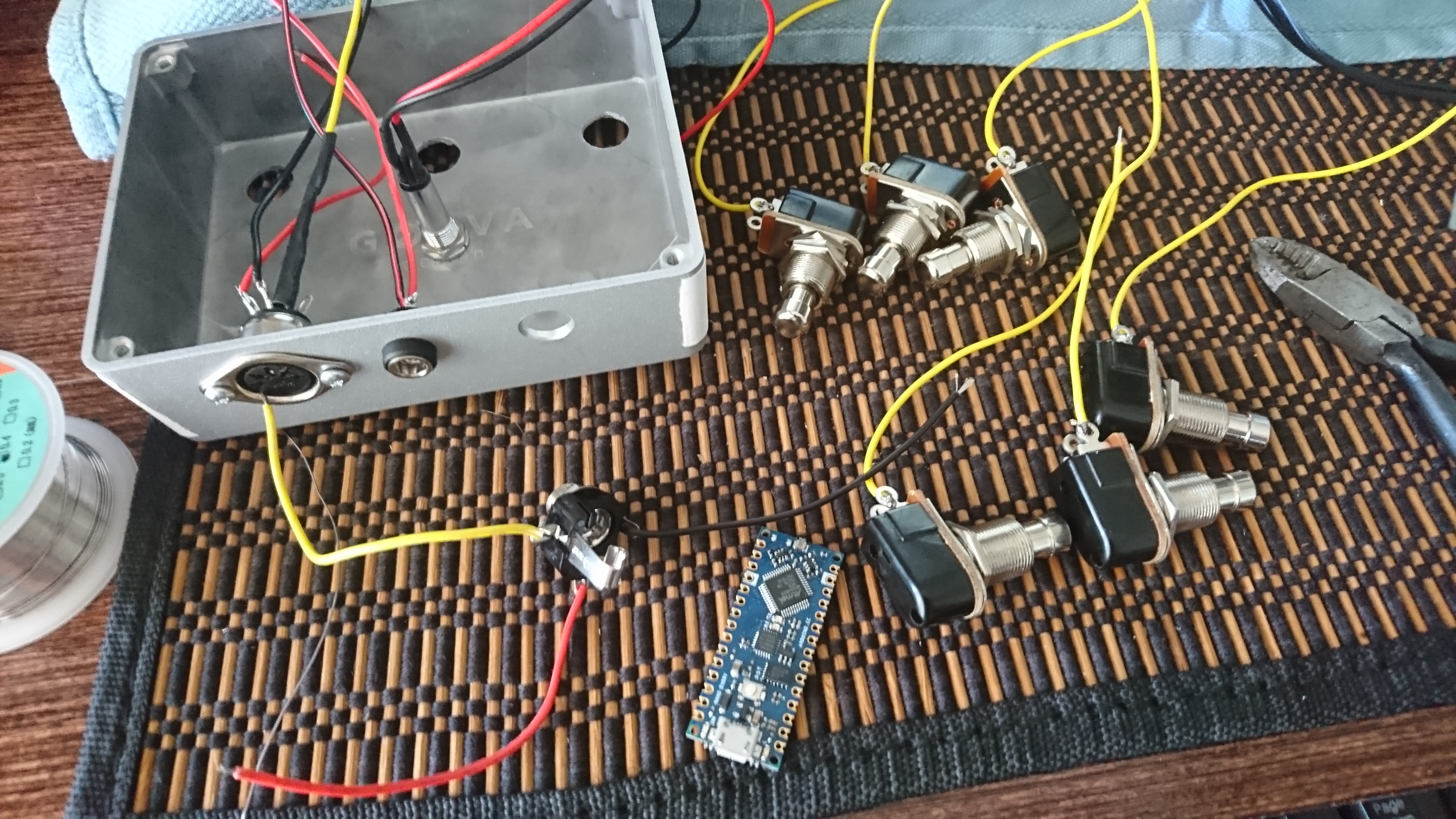
Then you just wire everything up. The Board only has 2 ground slots.. so I run from the Power Jack to one of them.. and then I make a big happy common ground and connect it to the other one.
I wire the LED to 3.3V, so if the board has power, the light is on.
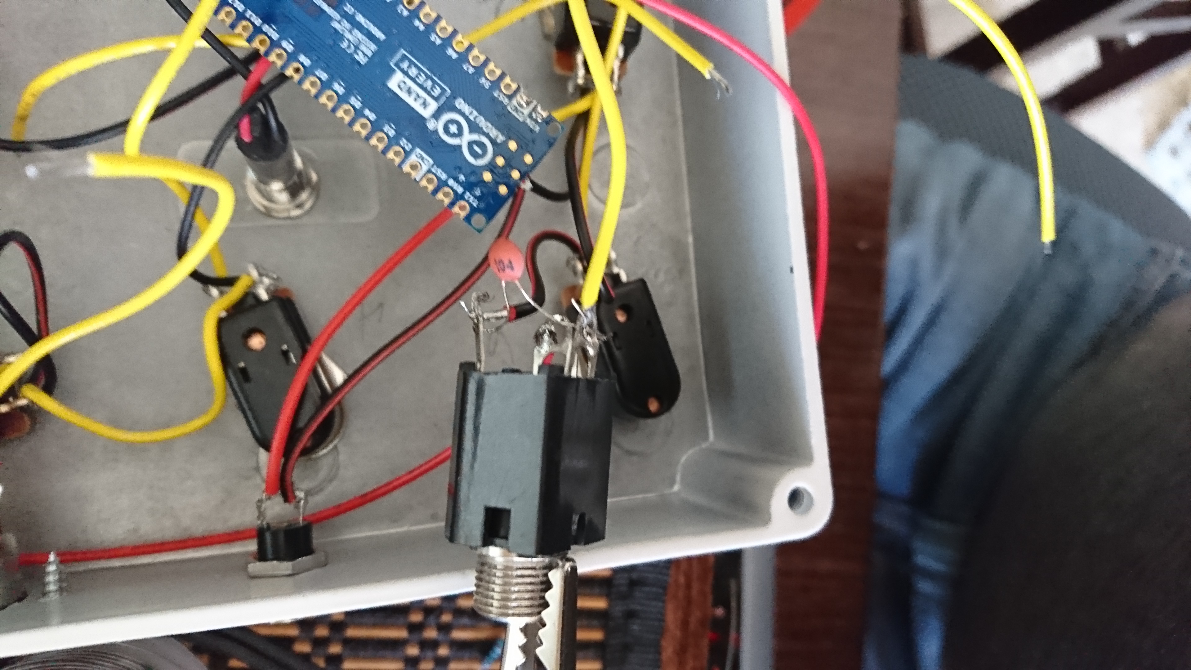
The Expression jack is wired in one of 2 standards. I use
5v- SLEEVE
A0- TIP
Ground to ground.
I put a 0.1 uF cap between the tip and ground. Why? to stabalize the jitter. I shouldnt NEED this, but I was getting a little noise and this fixed it.
Another look
Here is a final glam shot. The flat back is great. I use some 3M mounting tape to pin it down.
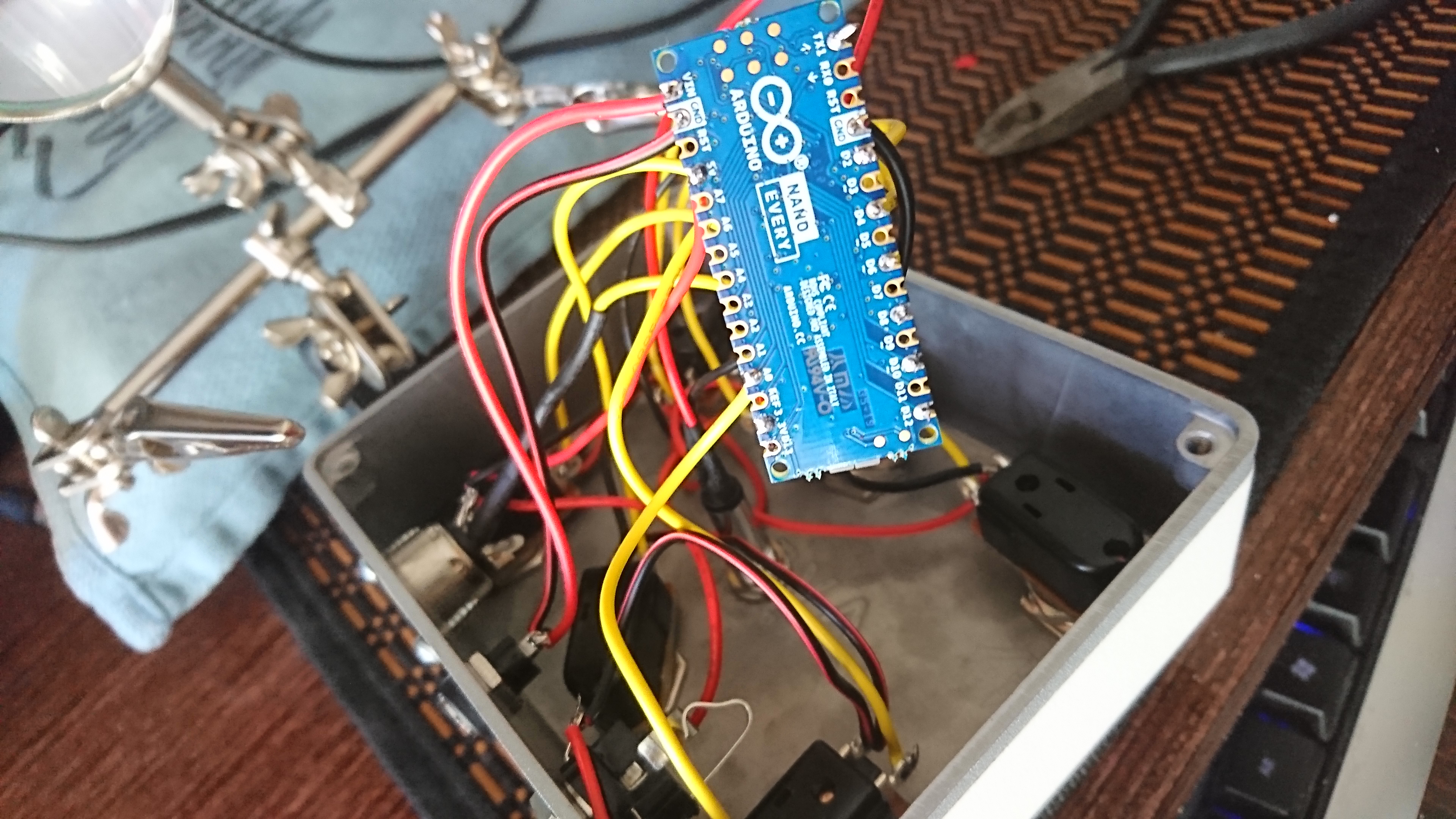
I use some 3M mounting tape to pin it down.
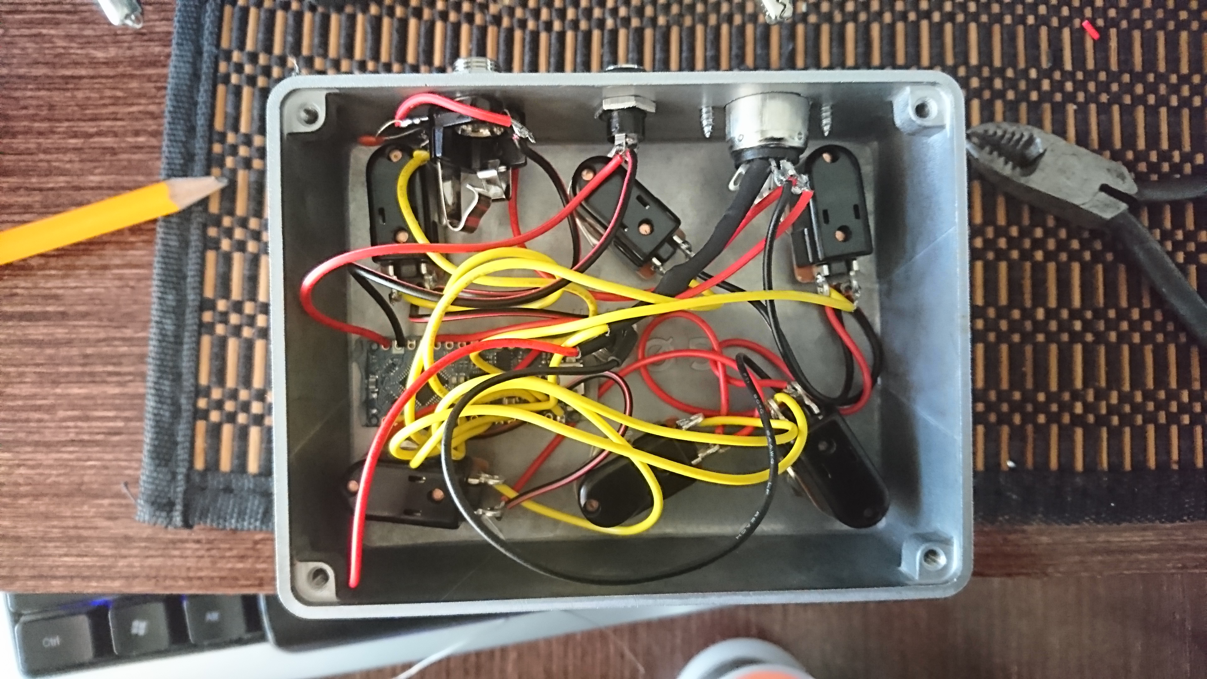
Tighten everything down, and there she is!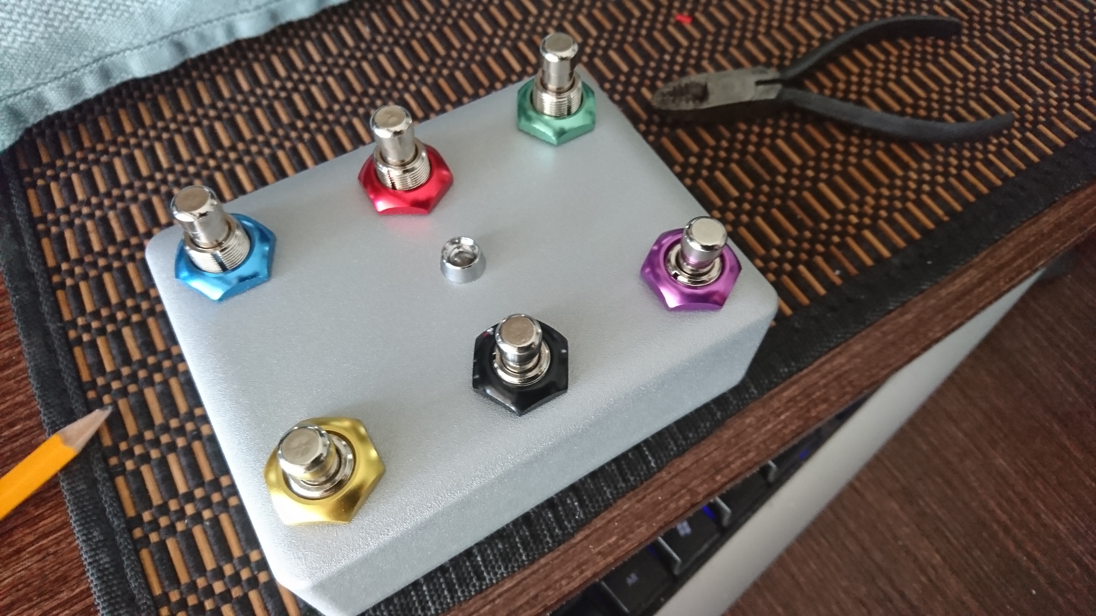

Setting it up on the H9 side is straightforward. Just assign CC and PC to what you want.
Here is the CODE. I have annotated it, so it should be easy to adapt.
If you make one, or you want me to make you one- find me on the ET boards or on Instagram.
//midi.controller for eventide H9
//by Cameron Newell @the.nw.enterprise, https://thenorthwestenterprise.com/
//Library Source https://github.com/tttapa/Control-Surface
// Dependency library should also be installed: https://github.com/PaulStoffregen/Encoder
// manually install latest one for Nano Every
// Built for Ardruino NANO EVERY. tested on NANO EVERY

#include <Control_Surface.h> // Include the library

// Instantiate a MIDI interface
//USBDebugMIDI_Interface usbmidi(115200); // for serial monitor in ide
HardwareSerialMIDI_Interface serialmidi = {Serial1, MIDI_BAUD}; //for normal operation (Serial1 for Nano EVERY, Serial for nano)

/* Instantiate PCButtons that read the inputs from a push button and sends out a MIDI Program Change message when they are pressed.
Ex: =   {**PHYSICALPIN**, {**PCHEXVALUE**, CHANNEL_#},};
HEX is fine http://www.midisolutions.com/MIDI%20Solutions%20MIDI%20Delay.pdf
*/
PCButton pcBtn0 = {12, {0x00, CHANNEL_1},};  //Upper Left TUNER Preset 0
PCButton pcBtn2 = {10, {0x02, CHANNEL_1},};  // Back Middle Preset 2
PCButton pcBtn5 = {8, {0x05, CHANNEL_1},};  // Back Right Preset 5

/*Hotswitch or other cc function will fire 127 on press and 0 on release by default. This is overridable. Use a momentary switch, like the others.
Assicn CC number from here, precede HEX with 0x
https://www.midi.org/specifications-old/item/table-3-control-change-messages-data-bytes-2
Ex: = {PHYSICALPIN, {**CCHEXVAL**, CHANNEL_#},{ VALUEWHNPUSHED, VALUEWHENRELEASED }};
*/
CCButton button8 = {6,  {0x10, CHANNEL_1},};  // Left Front hotswitch  CC#16
CCButton button6 = {4,  {0x11, CHANNEL_1},};  // Mid Front Decrement  CC#17
CCButton button4 = {2, {0x12, CHANNEL_1},};  // Right Front Increment  CC#18


// Setup for an Analog pot for an EXP pedal on cc #11
// Wiring is 5v on RING, pin to TIP and ground to ground
CCPotentiometer potentiometer = {A0, {0x0B, CHANNEL_1} // CC#11, pot wired to pin A0
};

void setup() {
Control_Surface.begin(); // Initialize Control Surface
}

void loop() {
Control_Surface.loop(); // Update the Control Surface
}