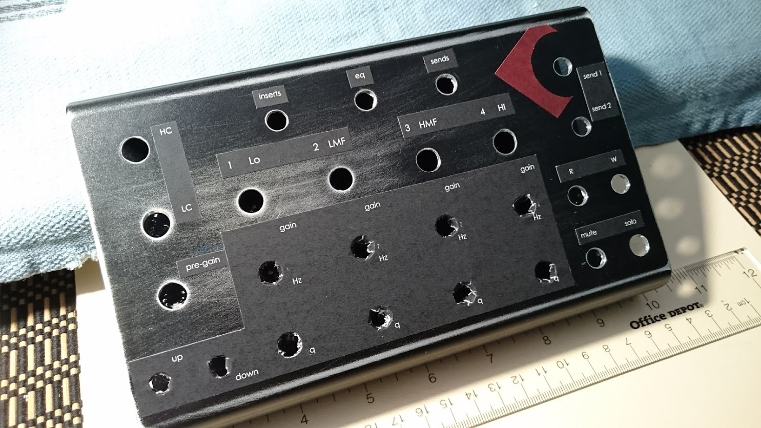
OK – so I love gear, obviously.. This writeup is IN PROGRESS.. so don’t hate. Oh wait- comments are disabled 🙂
I record and mix using Cubase 9, and I always have this one little hiccup- the EQ section. I want tactile control, not mouse control.
I had been using an Arturia Beatstep, which is fine.. except the knobs are horizontal, and I find myself glancing down at the controller, which distracts me from listening. So I want a controller than matches what I see on the screen, visually. Vertical columns of knobs for Pre-EQ, 4 EQ Bands, and a couple Sends on the right. Like this:
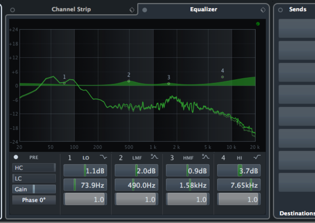
Of course I had heard of DIY MIDI Controllers. So I made one. Here is a tutorial… in case you want to do the same!
—————————————————–
PARTS LIST (obv you can customize):
1 x Ardruino Mega board (actually a knock-off, probably not the best choice in the end) AMZ $15.
17 x Rotary encoders AMZ $1.50/each.
9 x momentary panel-mount buttons AMZ $0.60 ea
17 x KNOBS- I spent ~$20, but you can choose any you want! AMZ AMZ
Some x prototype PCB boards AMZ $7
1 x An Old Hard Drive Enclosure – $0
1 x cheap USB MIDI converter AMZ $8
Wire, Solder, etc.. all in my house already.
——————————————————-
–A NOTE ON THE BOARD
So . . this was a first time thing for me, and a learning experience. There are better boards to get.. I chose the Mega because it has a lot of pins.
Each rotary encoder needs 2, and each button 1.. so I needed more than 50 pins.
There is a thing called MULTIPLEXING to make more out of fewer pins.. but I didn’t learn it, cuz I had enough. If you are like me- just get a board with enough pins for your controller.
The Mega in particular doesn’t have NATIVE MIDI out. So I did a trick I learned HERE. This works fine, and lets me use the USB jack in the enclosure, so its dope. . A different board might have native MIDI support.
THAT SAID- I used a Mega.
First things first- I hooked up some encoders and switches and proved I could do it. It was actually easy.
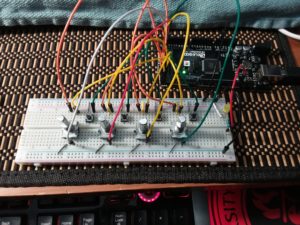
I based my code on the library here: https://github.com/tttapa/MIDI_controller- but I will enclose my code at the end.
Hardware wise. I didn’t do ANYTHING fancy. No Interrupts, no pull-down resistors.. no nothing.
What I did is PCB soldered my rotary encoders onto these little boards for easy of soldering, and so they would fit in a grid:
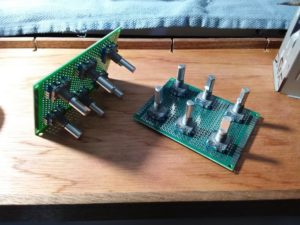
Looks harder than it was.
Here is a mockup I made.. mostly to decide on spacing and comfort:
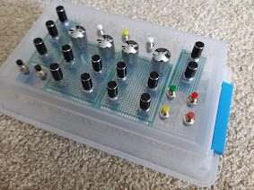
Then came the actual HARD part- the enclosure.
I had an old External hard drive that I sacrificed.
I used one of the PCBs to make a little drill template..
and did it all by hand. 1/64th at a time:
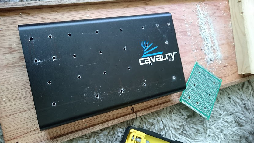
I was lucky- this enclosure fit PERFECTLY what I was doing.
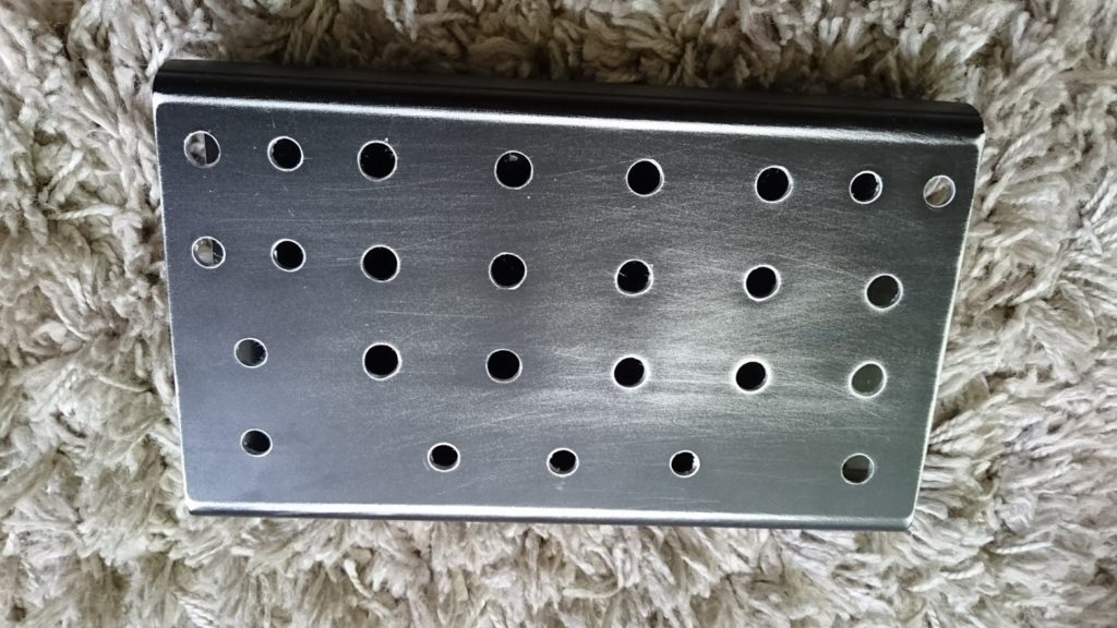
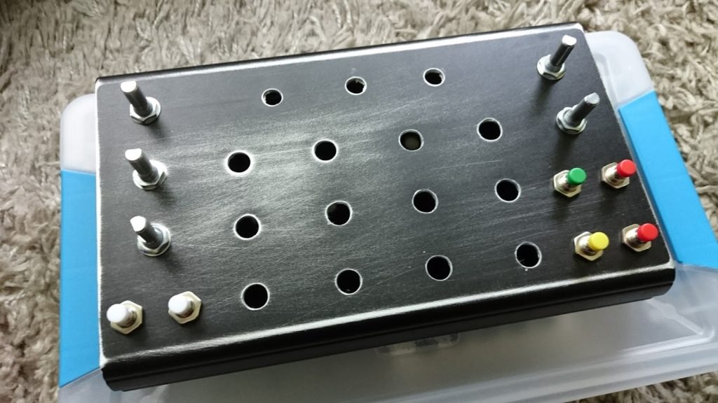
It also has a little button with an LED on the side that I used for swapping the MIDI channel- though that is totally optional.
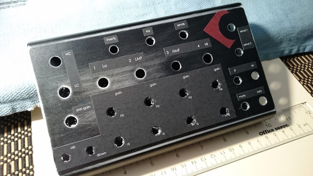
The labeling is pretty LO-FI.
I might do a proper finish job someday.. but for now it’s printed paper and rubber cement. with some coats of laquer over it.
Here are some final product pics.
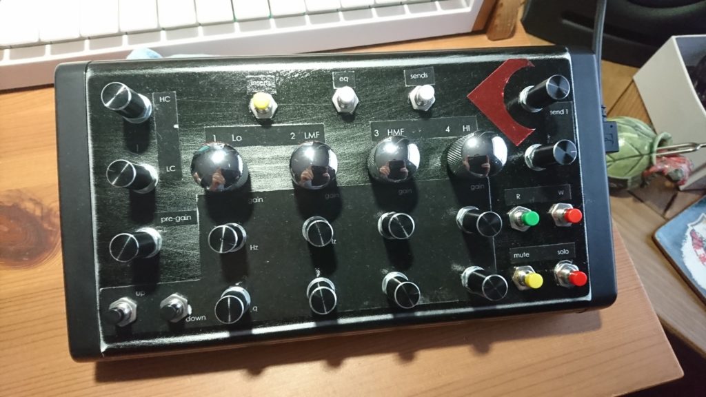
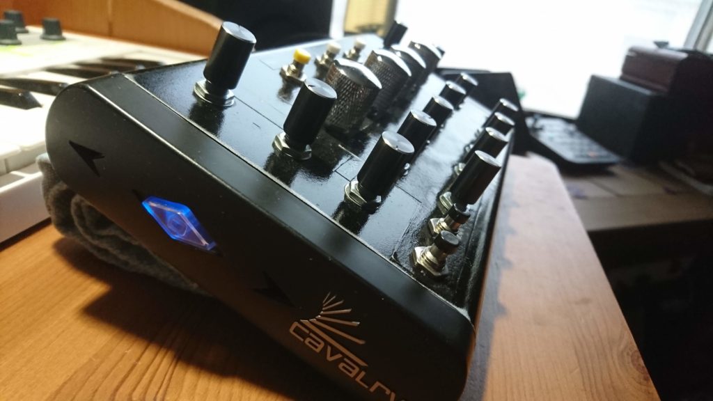
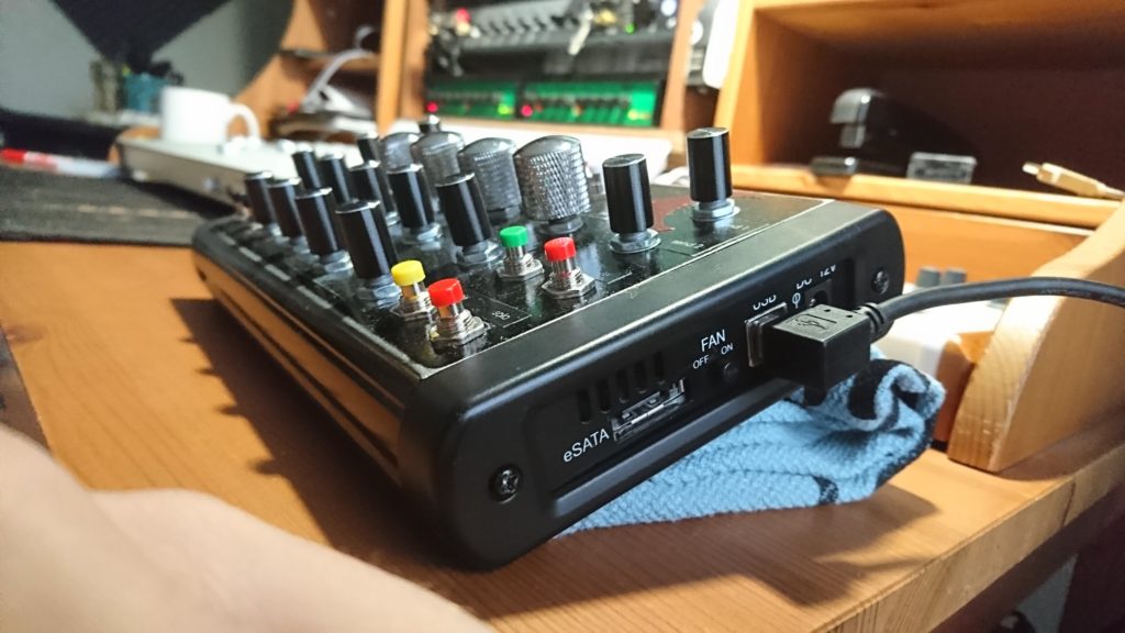
Obviously, in Cubase I just assign everything under the Generic Remote.
Once Hang-Up… the PreGain, HC and LC can’t be directly controlled… I have to use Quick Control. If only they supported them under the generic remote!
Here is a copy of the generic remote map
https://thenorthwestenterprise.com/files/CubaseController.xml
On the ARDRUINO side…- this library is required.. here is the version I used:
https://github.com/tttapa/MIDI_controller/releases/tag/3.1.0
Here is a link to my code- I will attach it below, as well.
https://thenorthwestenterprise.com/files/MIDI_Controller_WORKING_COMPLETE.ino
AND THAT IS IT! It works, great, with the exception of the pre section, cuz not supported in generic remotes. Holla at me on the cubase or eventide forums if you have questions!
———–CODE HERE
/*
 This is a sketch for Rotary encoders and pushbuttons, with a latching swith to flip the MIDI channel for an additional bank of functionality
 Heavily adapted from code and library Written by Pieter P, 22-08-2017
 https://github.com/tttapa/MIDI_controller
 */

#include <MIDI_Controller.h>

/* Instantiate a MIDI interface that sends debug messages to the IDE's USB Serial port (Serial Monitor) ctl/shift/M */
 //HairlessMIDI_Interface midiInterface; //UNCOMMENT if I am using Hairless to monitor
 // USBDebugMIDI_Interface midiInterface(115200); //UNCOMMENT for serial monitor in ide

/* channel MIDI settings here */
 const uint8_t Channel = 4; //set initial midi channel

/* How many channels to add on selector toggle. Pressing the button on Pin 2 will add this number to the MIDI CHANNEL */
 Bank bank(1);

/* Define all rotary encoders here- {pins x2, controller number in Hex, channel as defined above, Speed Multiplier, Type, Sign Mode}
 ROTARY ENCODER NOTES:
 If you are using a jog wheel, use JOG, if you are using a normal encoder
 (for normal controls like EQ or volume etc.) use NORMAL_ENCODER.
 If you have strange results in your software, try a different relative mode:
 TWOS_COMPLEMENT, BINARY_OFFSET or SIGN_MAGNITUDE.
 If the control works, but it goes in the wrong direction, swap the pins A and B of the encoder
 (either physically, or by swapping the pin numbers in the RotaryEncoder constructor).
 */
 RotaryEncoder encoders[] = {
 {67, 66, 0x00, Channel, 1, NORMAL_ENCODER, TWOS_COMPLEMENT},
 {65, 64, 0x04, Channel, 1, NORMAL_ENCODER, TWOS_COMPLEMENT},
 {63, 62, 0x06, Channel, 1, NORMAL_ENCODER, TWOS_COMPLEMENT},
 {4, 5, 0x0A, Channel, 1, NORMAL_ENCODER, TWOS_COMPLEMENT},
 {7, 8, 0x0C, Channel, 1, NORMAL_ENCODER, TWOS_COMPLEMENT},
 {53, 51, 0x10, Channel, 1, NORMAL_ENCODER, TWOS_COMPLEMENT},
 {49, 47, 0x12, Channel, 1, NORMAL_ENCODER, TWOS_COMPLEMENT},
 {45, 43, 0x40, Channel, 1, NORMAL_ENCODER, TWOS_COMPLEMENT},
 {31, 33, 0x42, Channel, 1, NORMAL_ENCODER, TWOS_COMPLEMENT},
 {27, 29, 0x44, Channel, 1, NORMAL_ENCODER, TWOS_COMPLEMENT},
 {23, 25, 0x46, Channel, 1, NORMAL_ENCODER, TWOS_COMPLEMENT},
 {48, 46, 0x48, Channel, 1, NORMAL_ENCODER, TWOS_COMPLEMENT},
 {44, 42, 0x4A, Channel, 1, NORMAL_ENCODER, TWOS_COMPLEMENT},
 {40, 38, 0x4C, Channel, 1, NORMAL_ENCODER, TWOS_COMPLEMENT},
 {30, 32, 0x4E, Channel, 1, NORMAL_ENCODER, TWOS_COMPLEMENT},
 {26, 28, 0x50, Channel, 1, NORMAL_ENCODER, TWOS_COMPLEMENT},
 {22, 24, 0x52, Channel, 1, NORMAL_ENCODER, TWOS_COMPLEMENT}
 };

/* Define all buttons here.. they fire noteon/noteoff --{pin, Note in Hex, Channel.
 Not much to talk about here. There should be a way to make these PC messages, but I don't know how.
 */
 Digital buttons[] = {
 {69 ,0x27, Channel},
 {68 ,0x24, Channel},
 {3 ,0x11, Channel},
 {6 ,0x12, Channel},
 {9 ,0x13, Channel},
 {10 ,0x14, Channel},
 {11 ,0x15, Channel},
 {12 ,0x16, Channel},
 {41 ,0x01, Channel},
 {39 ,0x02, Channel},
 {37 ,0x03, Channel},
 {35 ,0x21, Channel},
 {52 ,0x25, Channel},
 {50 ,0x22, Channel},
 {36 ,0x26, Channel},
 {34 ,0x23, Channel}
 };

void setup() {
 // This controls the TOGGLE SWITCH on Pin 2 that flips MIDI Channels
 bank.add(encoders, Bank::CHANGE_CHANNEL); // When the bank setting is changed, change the channels on all the items I created above
 bank.add(buttons, Bank::CHANGE_CHANNEL);

pinMode(2, INPUT_PULLUP); // software pullup of the pin. If it is on a different PIN.. change that here, and below in the loop.
 }

void loop() {
 // Read MIDI Channel Selector
 if (digitalRead(2) == LOW) // Must assign switch pin here as well. Two places total. using a constant broke the sketch, idk why
 bank.setBankSetting(1); // Add the abovereferenced number to the MIDI channel
 else
 bank.setBankSetting(0); // Add nothing to initial MIDI channel

// Refresh the whole encoder (check whether anything has changed since one microsecond ago, if so, fire MIDI)
 MIDI_Controller.refresh();
 }
